First off I'm a long time reader of this thread (still haven't read everything yet so please give me a break if it has been mentioned before) and new to inspire and to quad copters in general lol. Just bought a used one online
")
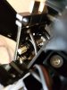
Anyway, I noticed everyone is saying to wire the auxiliary battery leads to the dji battery itself. Why? From the photos and a tear down video of the dji battery, you are wiring directly to the output anyway... Would save some big hassle making multiple battery mods vs a one time wiring right on the AC and adding a comparator circuit to prevent auxiliary batt from powering on the AC prematurely and voltage matching (with vdrop buffer) so as not to tax the dji battery when using standard 4.25v vs 4.35v cells at start of flight.
Also, reading from posts people are having issues with the dji battery depleting too early causing automatic landing. Isn't it possible to build a circuit to switch between packs? IE modify the power lead on the AC such that power from the dji battery will trigger auxiliary to supply power first. Then, at a predetermined voltage, switch to the dji pack. Redundancy can be achieved by maintaining a reserve voltage on the auxiliary pack.
Just a thought. I have no experience in building any of these things, but I do enjoy the read. Going to be learning how to fly the inspire next week, hopefully I won't crash it..
Happy modding everyone!