Welcome Inspire Pilots!
Join our free DJI Inspire community today!
Sign up

Battery Mod Info

Status
Not open for further replies.
23:57 to 10% with the Pro + X5R and TP 2700's. Better than the 23:09 with the TP 3500 LiHV's, but still 1:03 short of my 25min goal with the Pro and X5R.

Probably try 2200's next.

57160cbace0b3ae2e9a7569e85e70053.jpg
c5081a7763702c61b5b91d879c846eb1.jpg
 
If you can put it back together and they can't tell then who's the wiser?
Nice photos and disassembly. External cell monitoring cable?
 
^^ I did the batteries as the I1 is still in warranty. I modded 7 TB48's in a couple of hours - it's no big deal. Did one start to finish beforehand, establish a 'process'..

Here's what I did, couple of bits I did I haven't seen elsewhere.

Pop the lid off.
Undo 4 screws & detach board.
Cut hole and enlarge (dremel 3.2mm endmill). I left 2-2.5mm material between bottom of hole (slot) and edge.
Butcher side of case down to pcb level where wires will exit. (dremel same cutter)
Remove tape and clean board - remove blue stuff. (5mm brass wire brush on dremel) battery IS off (;>)
Solder wires. Tin board and wires first and it will all flow nicely. I used 40W with spade tip. Keep wires absolutely flat. Pin the wire down in place with something non-metallic before actually soldering. Route +ve towards the back.
Replace board and do up four screws
Re-tape exposed connections / pcb.
Lid back on.
Check continuity / resistance with multimeter
Fill void at side where cable is with hot melt.

I used 14swg silicon wire.
There was no need to 'raise' the board by hacking the mounts, the top popped back on perfectly.

About 20 minutes or so each.
Hi , I have a old battery and would like to the mod.Do you have any pics exactly where you Solider the wire too.. It would be a big help to me .
 
Thanks I saw that. Do I Solider directly to the wire positive posts and Megan directly to the wire positive posts and Neg wire post. I can't tell from the pic . ( old eyes)..
 
Sorry driving home from work . Talking into my iPhone ..
No, no need to solder onto the original cables. There is plenty room towards the front above the plug contacts for two cables if required.
I routed the +ve towards the front, not the -ve as shown in the how-to. I think this is easier
 
For those of you guys wiring the leads directly to the bird, how are your mounting you aux batteries?
 
Hi everybody :)
I did the mod directly to the bird.
just finishing up the bodypaint :D

I did pics but I am afraid I missed the (was so excited !!!) that I did not do the pics from the soldering on to the contact but can explain in detail.

I will try to load up the pics - have to grab them off the phone.
it did take a bit of time but I managed to get the pics. now updating my iphone to 9.3 and hope I am doing nothing wrong.

now the pics

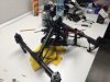
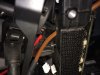
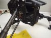
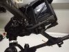
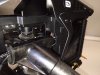
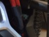
the first shows the disassembly. I striped her. since I already done it once it is not so hard.
first you take of the nose. - undscrew the bottom phillips screws under the camera gimbal plate, then the four that hold the nose to the top cover. for that you have to pull off the gimbal plate of course.

second: then you unscrew the side screws which are the holders which is a torx T9 with a total of 8 screws.
once you have done that you move to the butt of the lady and take out the last two from the side.

third step: then you take another small tiny itsi bitsi philips screw driver and take out carefully the four that hold the the very back (the one with the big *** LED. you have to fiddle a bit to take it off due to the ribs.

fourth: slowly work your self around the bird and pop the top off but behold and carefully as the GPS cable is still pluged in. so you take out the little sucker and voila :D the top is off :D

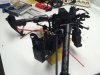
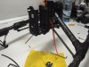
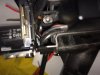
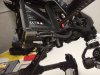
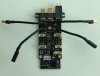
fith step: you will see the "brain" or the main and only controller as our lady is not so smart to have two of them in case one chooses to die on us midflight - but that is another story...
so you unplug all the cables from the "brain" and you will also see four small screws holding it to a kind of rib cage - that was what I managed to break :)
the screws are TORX T6 with which you take off the brain from the cage.

sixth step: then you go to the bottom of the bird underneath and unscrew the four that hold that rib cage. once all is loose you will be able to pull the cage off which is holded by rubber bumps that hold it in place.

seventh step: you then look at the battery compartment and find that it is also loose as the rib cage was holding the whole thing in place.

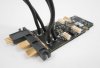
eighth step: so you pull the battery compartment off a bit but before you do that - I forgot one step- you unscrew the battery PCB from the body which are five screws within the compartment.

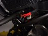
ninth step: once everything is loose and the PCB is off - I forgot another thing- you have to unplug 6 cables (three on each side) - don´t worry it will be easy to get it back in - you then have enough cable to pull a bit. once you do that - all gentle and calmly - you will notice that there are rubber plugs holding the cable in place in the part that moves when you put the leg up.

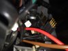
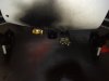
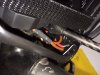
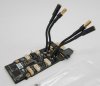
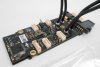
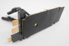
tenth step: you can now carefully pull the PCB out a bit to solder the cable on there.
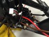
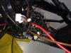
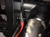
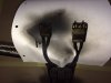
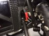
since I grew up in a cable harness manufactury I ultrasound soldered two cables to make an "Y" since I will be using 6S so I need parallel connections with XT90 I have used.
for that I used 2.5mm thickness and put that together with two 4mm cables and soldered the 2.5mm to the bottom of the connectors which fit right under and are flexible enough put the PCB plate back to its place. - anything bigger would not work for me as the cable I used is not silicone.

reasembling:
do all the steps backwards. start by putting back the PCB and screw the five screws back. then you replug the cables and put the body sceleton back in place on the rubber bumpers, screw back the rib in the front by first putting it on the rubber bumpers there too and then fitting the bottom back on and secure it with a screw or two so it won´t move away while you operate the rest of the bird.

then you screw the brain back on fit the cables back and start to but the top back. take caution on the middle part (where the battery connections are to have it fit in the right position) otherwise it will not snap on. - before you do that you plug in the GPS and then work yourself from the front to the back snapping it back on on the sides. - remember that no force has to be used. all comes off and goes on very easily. -

once the top is on and sits where it should be you can go on with the nose. FIRST put in the two bottom screws before you forget them and already put on the gimbal plate and bite your butt having to take it off again. - here the remainder-

so then you fit the four front screws with the longer ones on the top and the short ones on the bottom. put back the sides and the butt with the LED.

and then you are finished..
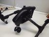
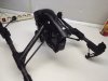
I took the chance and painted mine in a happy black which looks like the pro black version now... :D

if I missed something or anything is unclear please ask and I will try to get more into detail. - know this ***** by heart by now :D

cheers.


EDIT: I made a little photo session with her as my iPhone did update after three unsuccessful tries and me starting to believe in god to make it happen that I do not have to restore my phone although I did do a backup upon hitting the update button :D

I will have to post the pics in another post as this one is maxed out :)
 

Attachments

  • IMG_1200.JPG
    IMG_1200.JPG
    1.6 MB · Views: 198
  • IMG_1201.JPG
    IMG_1201.JPG
    1.5 MB · Views: 183
  • IMG_1202.JPG
    IMG_1202.JPG
    1.3 MB · Views: 183
  • IMG_1203.JPG
    IMG_1203.JPG
    1.6 MB · Views: 182
  • IMG_1204.JPG
    IMG_1204.JPG
    1.7 MB · Views: 180
  • IMG_1205.JPG
    IMG_1205.JPG
    1.5 MB · Views: 175
  • IMG_1206.JPG
    IMG_1206.JPG
    1.7 MB · Views: 184
  • IMG_1207.JPG
    IMG_1207.JPG
    1.8 MB · Views: 185
  • IMG_1208.JPG
    IMG_1208.JPG
    1.9 MB · Views: 180
  • IMG_1209.JPG
    IMG_1209.JPG
    1.5 MB · Views: 177
Last edited:
here the latest pics of the new bird. she looks nice, doesn´t she? - Damon, not only you have a black one :p

I tried to make pics from all around her. showing the most intimate parts :D - what is that, drone porn after battery porn LOL HA HA HA

also same here, if you would like to have closeups of anything let me know and I´ll take her apart again to make the pics if needed.
 

Attachments

  • IMG_1210.JPG
    IMG_1210.JPG
    597.6 KB · Views: 123
  • IMG_1211.JPG
    IMG_1211.JPG
    476.6 KB · Views: 119
  • IMG_1212.JPG
    IMG_1212.JPG
    504.8 KB · Views: 119
  • IMG_1213.JPG
    IMG_1213.JPG
    551.9 KB · Views: 120
  • IMG_1214.JPG
    IMG_1214.JPG
    623.3 KB · Views: 119
  • IMG_1215.JPG
    IMG_1215.JPG
    370.4 KB · Views: 117
  • IMG_1216.JPG
    IMG_1216.JPG
    604.1 KB · Views: 120
  • IMG_1217.JPG
    IMG_1217.JPG
    497.8 KB · Views: 122
  • IMG_1218.JPG
    IMG_1218.JPG
    390.5 KB · Views: 127
  • IMG_1219.JPG
    IMG_1219.JPG
    407.5 KB · Views: 125
  • Like
Reactions: John Boylan
IMPORTANT !!!!!

make sure ALL of the six connectors that are on the battery PCB are reconnected and secured. I managed to miss one (pic below) and it will not start up the motors bringing up "error 45 contact DJI service support"
reconnected and all is well.

it's the little white **** behind the red cable. it looks like its in but it wasn't bringing me up the error I mention in the line above.
 

Attachments

  • IMG_1223.JPG
    IMG_1223.JPG
    291.9 KB · Views: 88
  • Like
Reactions: John Boylan
Could you use one of the pictures I found online of the Inspire 1 main board and show or explain where you made the solder connections to the actual board?
 

Attachments

  • InspireMainBoard11.jpg
    InspireMainBoard11.jpg
    72.5 KB · Views: 109
  • InspireMainBoard12.jpg
    InspireMainBoard12.jpg
    118.2 KB · Views: 105
  • InspireMainBoard13.jpg
    InspireMainBoard13.jpg
    89.4 KB · Views: 99
  • InspireMainBoard14.jpg
    InspireMainBoard14.jpg
    57.8 KB · Views: 100
  • InspireMainBoard15.jpg
    InspireMainBoard15.jpg
    30.3 KB · Views: 110
Could you use one of the pictures I found online of the Inspire 1 main board and show or explain where you made the solder connections to the actual board?

hi jores,

sure. the best pic is the last one. when you look at the board yoi see the battery contacts sticking out. beneth are the four motor cables that go into the frame when assembled.

now, at the contacts just where they meet with the board fits a 2.5mm cable just snug and bends just right so you can put the pcb back into place.

i will try to be mor exact. when you look at the contact and follow it from topp to bottom on the side where you can see the electronics of the board. at the lower part of the battery contact meeting with the board, that is where i soldered the cables.

i will take her apart again and make some close ups which reminds me of page 52 on the web based forum version in this thread a member made pics on how he did it and there you can see / make out how he has done it. i first tried with thicker cable and then went down. to 2.5mm which turned out to be good for placing and reasembling.

i hope my explenation was clear... if not let me know and i will take more detailed pics for you if needed. you have to fuse the cable that you want to solder from the front to the backto be able to solder it onto the pcb.

hope i could help and let me know if you need more detailed pics.
 
i ceopped the pic of the pcb for you. the junktion of contact and pcb is the spot where the canles fit inbetween. i soldered them to the side away from one another. meaning that the cable short end (being soldered to the pcb face eachother to the inner middle of the board.

edit: so when you look at my pic in this post then you would solder the positive cable onto the left with the longer side on the left and when putting it back together bend it in a little "s" shape to fit it into and next to the pcb and contact. the negative short side would face the positive short side making sure the do not touch.

hope that helped.
cheers
 

Attachments

  • image.jpeg
    image.jpeg
    2.8 KB · Views: 93
Status
Not open for further replies.

Members online

Forum statistics

Threads
22,295
Messages
210,755
Members
34,562
Latest member
adidasCampusShoes