
- Joined
- Dec 9, 2015
- Messages
- 756
- Reaction score
- 378
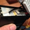
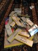
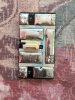
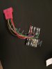
dear mad anglerhere are the pics i promissed
View attachment 6546View attachment 6547
hope they are ok. if not i will make some pics with my nikon for you or under our video microscope
let me know.
cheers
Sent from my iPhone using Tapatalk
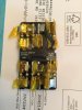
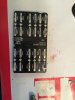
Top man thank you, I'm specifically Interested in the RH side of the top picture around the 4 large transistors in a row, are there any PN on them do you know ? Are the tracks visible on the PCB
Again really appreciate it [emoji3]
Sent from my iPhone using Tapatalk